
 Products

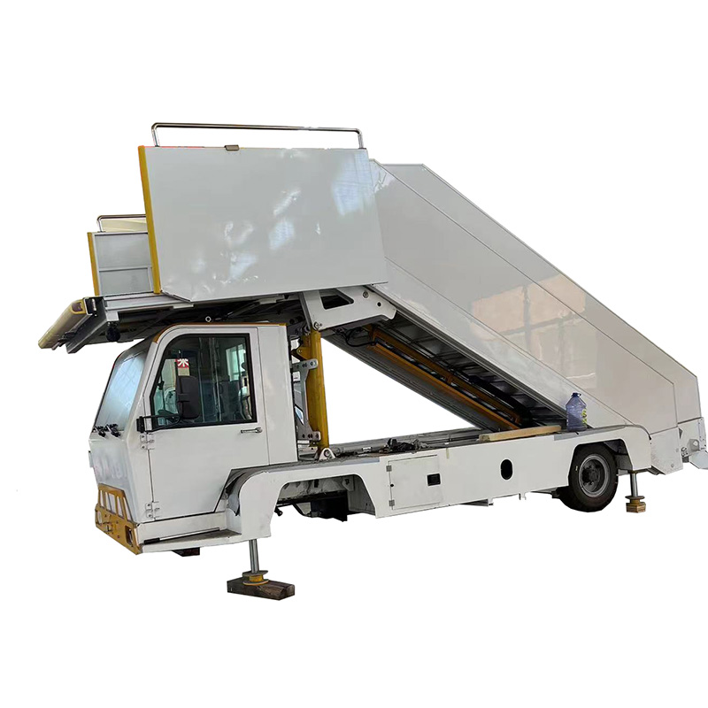
Catering Truck
01
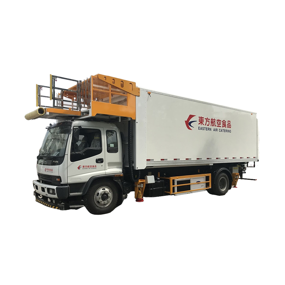
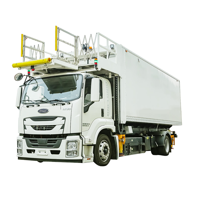
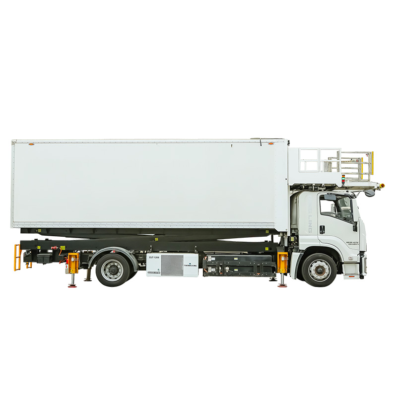
Catering Truck
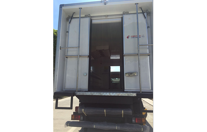
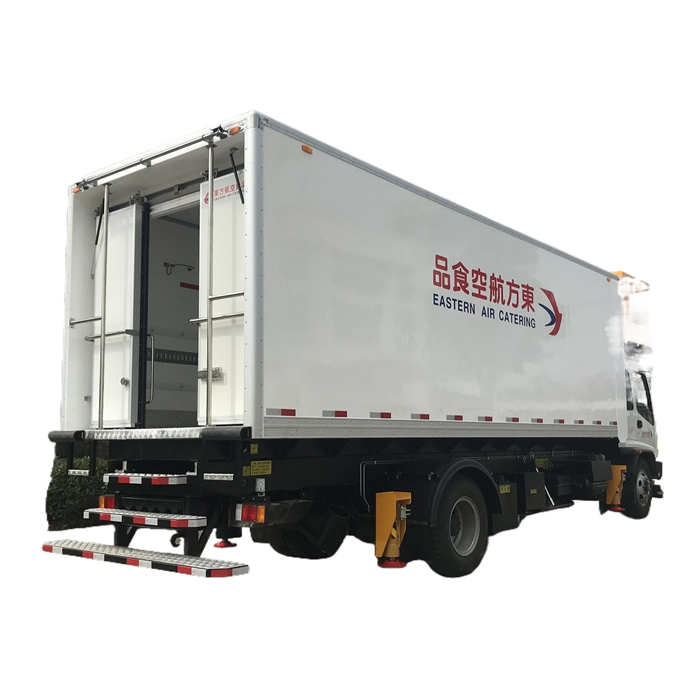
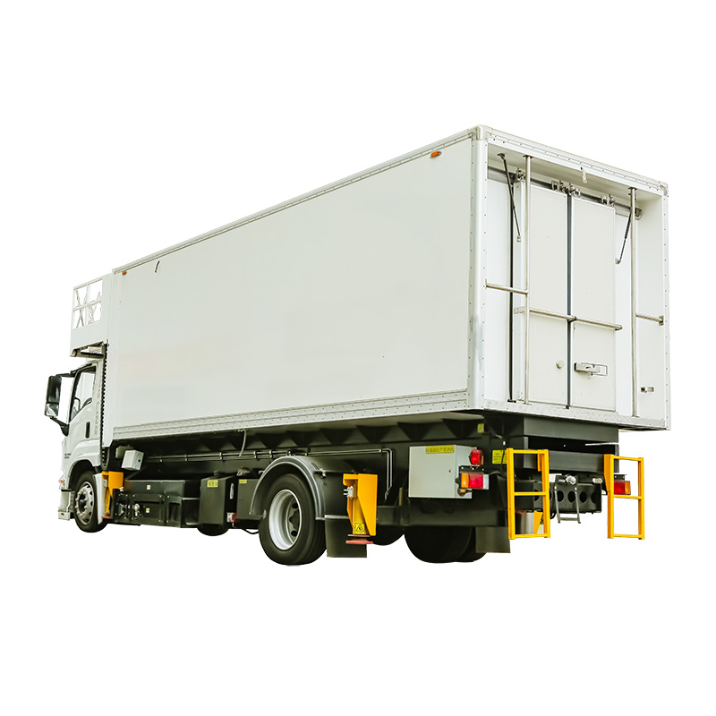
Slide door
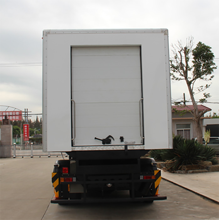
Roller door
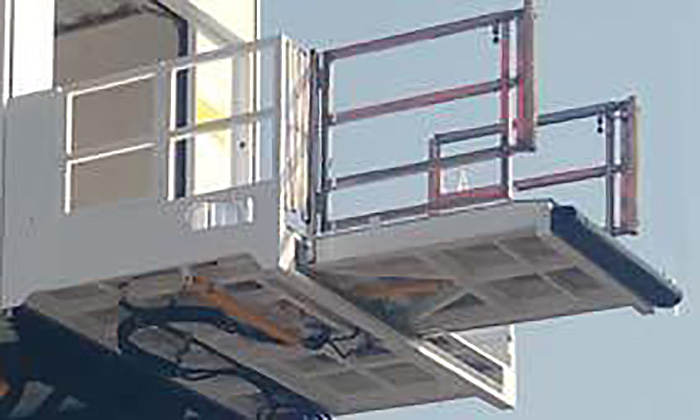
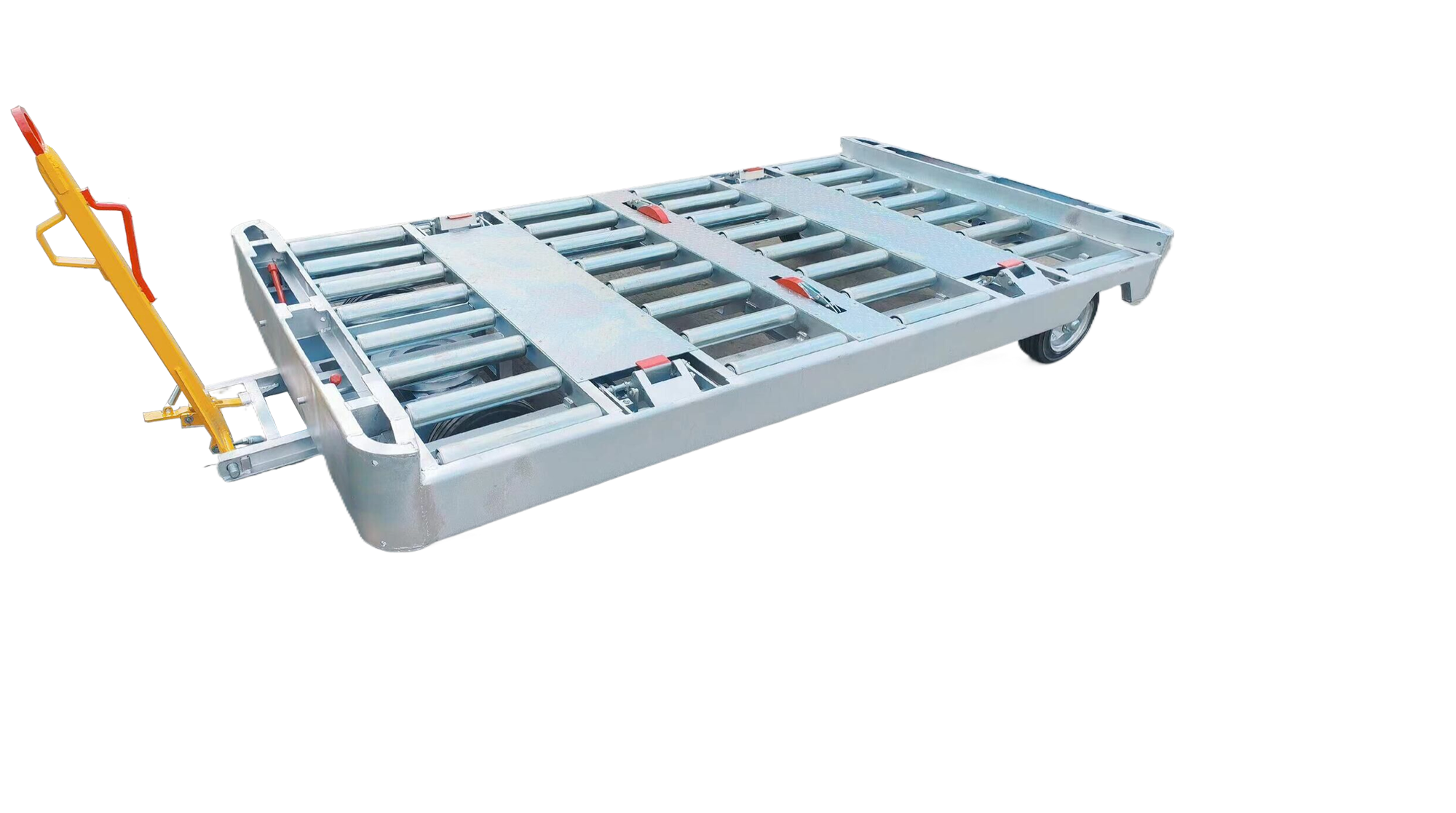
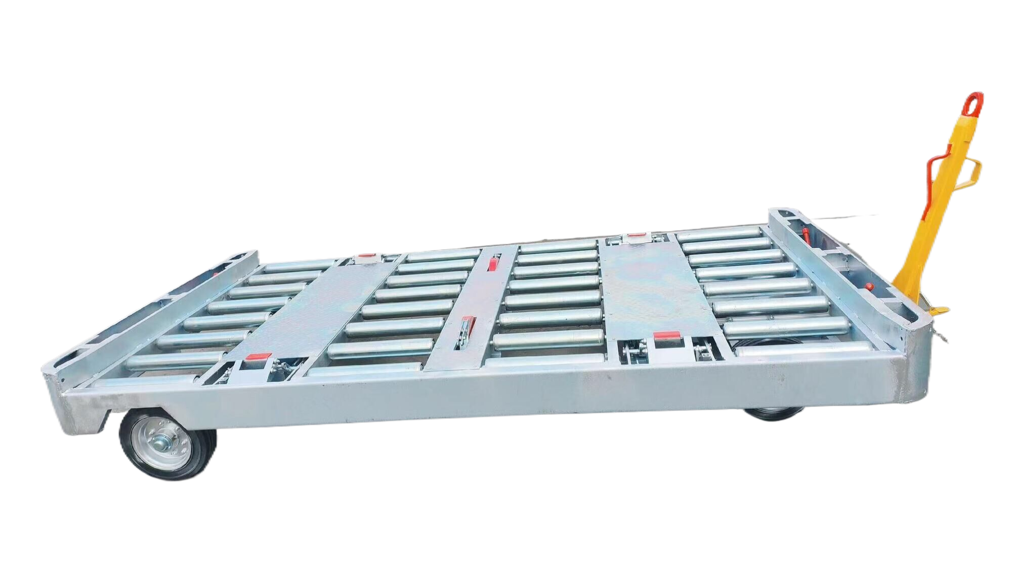
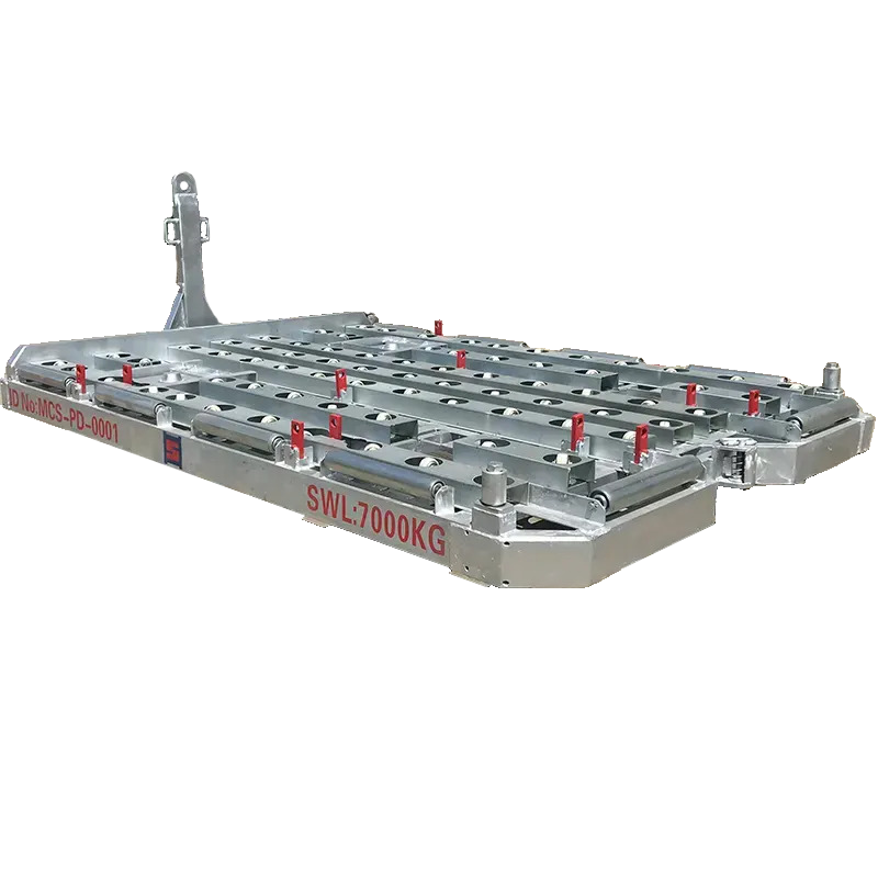
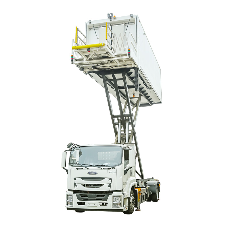
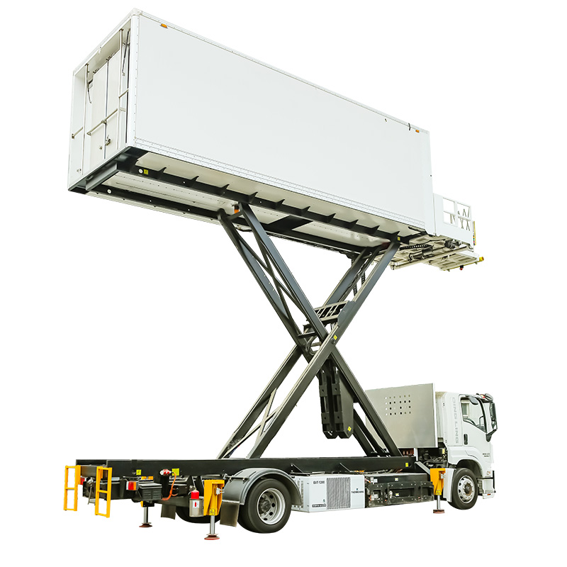
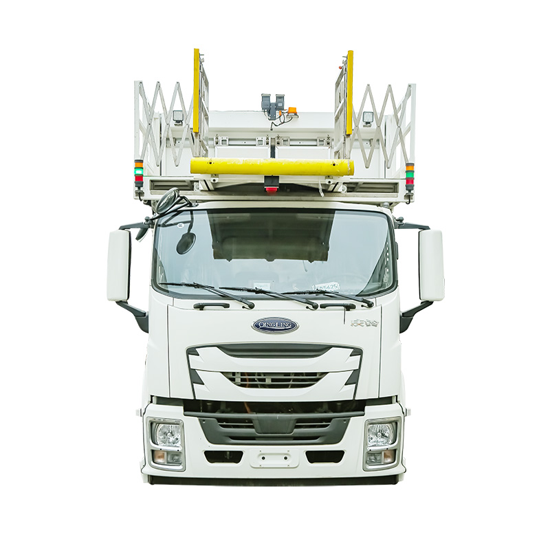
Platform
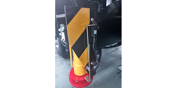
H type support
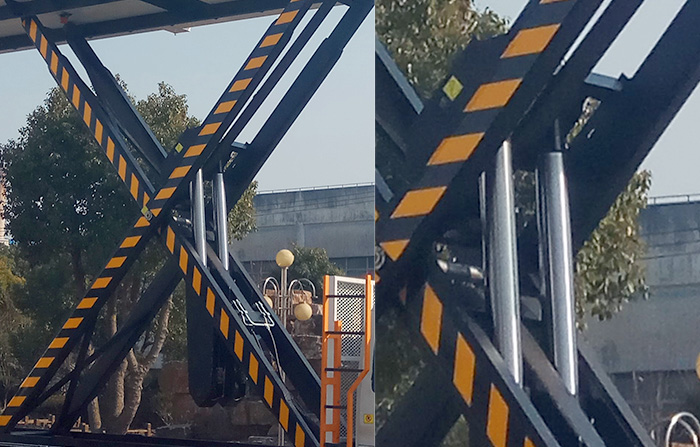
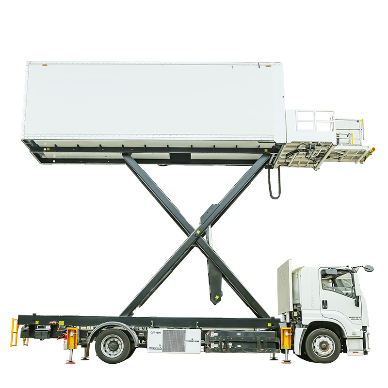
X type elevator structure
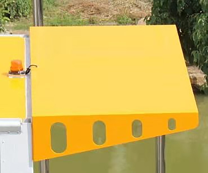
Canopy
Main technical parametersCHIDGE
| Chassis | ISUZU (LHD) |
| Overall dimension (L×W×H) mm | 9800×2590×3800 |
| Container dimension (L×W×H) mm | 7200×2480×2400 |
| Axle base mm | 5550 |
| Platform lift range mm | 2750~6000 |
| Fixed platform (L×W) mm | 2480×1400 |
| Platform left/right moving (L×W)mm | 1200×930 |
| Platform rear/forward (L×W) mm | 500×1080 |
| Ground clearance (L×W): Min mm | 1400 |
| Max. mm | 6000 |
| Total weight (kg) | 12830 |
| front axle (kg) | 5200 |
| rear axle (kg) | 7630 |
| Min ground clearance(mm) | 200 |
| Min turning diameter(m) | 18 |
| Max weight of container(kg) | 4000 |
| Max load of fixed platform(kg) | 1000 |
| Max load of movable platform(kg) | 400 |
| Transverse central distance between front and rear stabilizers (mm) | 5450 |
| Vertical central distance between front and rear stabilizers (mm) | 0~500 |
| Lifting time of container(S) | 70/55 |
| Contracting time of stabilizers (S) | 15 |
| Time for platform moving forward/backward(S) | 8/6 |
| Allowable wind speed | 8 |
| Max vehicle speed | 35 |
| Vehicle speed for approaching aircraft | ≤5 |
| Hydraulic oil | hydraulic oil 46# |
| Volume of hydraulic oil tank (L) | 180 |
| Volume of fuel tank (L) | 150 |
| Refrigerated unit | Carrier 750S |
| Engine type | 6HK1 |
| Max working pressure(Mpa) | 15 |
Structure overviewCHIDGE
Refrigerated aircraft catering truck is mainly consisted of: FVR Automobile chassis, supporting lug framework assembly, lifting trestle assembly, carriage assembly, platform assembly, refrigerating system, hydraulic system, and electric system etc.
1. Refer to FVR34P truck operation manual for chassis structure.
2. Supporting lug framework assembly adopts vertical supporting style, using hydraulic cylinder for supporting and contracting job, while supporting lug framework is combined with vehicle frame into one.
Note: supporting lug should be on when vehicle is not used.
3. Lifting trestle is composed of four high-strength rectangle steel tubes, and fixed into vehicle frame and carriage with long and short pins.
4. Carriage assembly is consisted of front and rear door frame, header, floor, left/right side plate and front/rear rolling door etc.
● Carriage plate should be made of special material for cooling vehicles. The plate adopts totally-closed PU jointing structure with out-inner layer of excellent glass-fiber composite plate and lining of rigid PU foam thermal isolation material; and the out-inner layer surface of food-grade advanced gel coat featuring excellent photo-protection, rain-erosion, gloss retention certified by LR, no need for any special treatment; and the lining of light advanced heat-isolated FVR structural shape. The insulation coefficient (W/㎡,K)≤0.45.
● Carriage composite board is fixed with carriage frame by rivet.
● The floor is laid with alloy skid-resistant aluminum plate, featuring skid resistant, clean and easy to clean etc.
● Rolling door is made of aluminum alloy, featuring fine sealing, flexible to open, light and handy, and inside & outside locks etc.
● Torsional spring is installed above rolling door, roller on the right and left of, lockable door below; and roller slot on sides of carriage door frame. The door should be unlocked to open it which shall be lifted by torsional spring; and the rolling door should be pulled down manually to lock up.
Note: when driving, the rolling door should be closed and locked up.
● In carriage, there are stainless steel guard plates and fixed belt of international standard, which is convenient to fix dining vehicle and food.
● Refrigerating system adopts Carrier 750S refrigeration units, meeting environmental needs; and refrigeration unit driven by independent tri-vortex diesel engine and AC 380V auxiliary motor with condenser installed outside of automotive frame, vaporizer on the top of middle carriage, and control system of microcomputer in cab for easy operation.
5. Escalator and hand lever are mounted on the rear of carriage for workers.
6. Platform assembly is consisted of stationary platform, left-right movable platform, front-rear retractable platform and guard fence.
● Stationary platform is installed with four rollers matched up with front end of carriage to make trestle lift carriage for driving platform up or down.
● Left-right movable platform is set in stationary platform and front-rear contracting platform in left-right movable platform; and all platforms are mounted with rollers. Driven by pressurized oil output by main pump, the platform is enabled to move right and left, and retract forward and backward by hydro cylinder.
Note: when the work is over, contracting platform should be in place.
7. Hydraulic system (fig.1 Hydraulic system schematic)
The system uses open, single-pumped, paralleled fluid circulating mode, consisting of actuating unit, control apparatus, actuator, helper and service fluid.
● Actuating unit
Active force comes from gear pump, namely engine driving PTO, and then PTO actuating oil pump for outputting service fluid.
Emergency pump is consisted of electric pump and hand-cranking hydraulic pump; and when electric pump does not work without electricity, hand-cranking pump could replace it.
● Control apparatus
Control apparatus includes pressure valve, direction valve and flow valve.
Pressure valve: consisted of relief valve and throttle valve.
Relief valve adopts solenoid piloted relief valve. Non-moving solenoid valve makes relief circuit in
the system and motorized valve closed, so relief valve adjusts the highest pressure of system.
Adjustable throttle valve is mounted on the back of manifold block, adjusting hydraulic one-way valve to change pressure, clockwise turning for pressure build-up, and vice versa.
Direction valve includes two electro-hydraulic directional valves, two hydraulic one-way valves, two one-way valves, and four hydraulic reversible locks.
Solenoid directional valve controls contracting or extruding of lift supporting lugs.
Hydraulic one-way valve makes fluid move in one direction.
Reversible hydraulic lock is mounted besides every supporting lug for ensuring to be locked in contracting or extruding position.
Flow valve adopts a one-way throttle valve to adjust carriage descending speed, clockwise turning for speed build-up, and vice versa.
● Actuator
Actuator includes carriage hoist cylinder, cylinder for supporting lug contracting or extruding and platform cylinder.
Platform cylinder uses two double-acting cylinders, and adopts hydraulic power station to control platform left-right moving and front-rear retractable.
Carriage lifting cylinder is of two one-stage plunger cylinders with lower supporting axle fixed on chassis, upper supporting axle on inner trestle, jacking structures adopting crossbeam trestle, and exhaust bolt mounted on the top of cylinder.
Supporting lug cylinder adopts four one single piston rods double-acting cylinders mounted on four supporting points of vehicle frame.
● Auxiliary devices
It includes fuel tank, filter, liquid indicator, pressure gauge, and hydraulic tube.
Fuel tank is made of 2 mm stainless steel, mounted with ablassschraube on the bottom.
Oil filter
Hydraulic air filter is mounted on the top of fuel tank.
Self-sealing oil filter: fuel capacity 160L/min, filter fineness 100um, mounted on the left of fuel tank.
Self-sealing pressure pipeline filter is equipped with by-pass valve opening pressure 0.4Mpa. When the filter element is blocked with differential pressure 0.35Mpa, transmitter (48W) makes switching signal.
Pressure gauge: type YN60, range of measurement 0~25Mpa, used for displaying system pressure.
Hydraulic tube: using welded joint and seamless hydraulic steel pipe, three-tier of steel wire made high-pressure hose with working pressure 32Mpa, operating temperature -25~+80℃; and pipeline sealing using O-type synthetic rubber seal with working pressure 32Mpa; and combined sealing washer with working pressure ≤40Mpa.
● Actions of actuators and electromagnet gain-and-loss table
|
Electromagnet Actions |
1DT |
2DT |
3DT |
4DT |
5DT |
|
|
Carriage |
up |
+ |
- |
+ |
- |
- |
|
down |
+ |
+ |
- |
- |
- |
|
|
supporting lug
|
releasing |
+ |
- |
- |
- |
+ |
|
withdrawing |
+ |
- |
- |
+ |
- |
|
Note: 1DT-electromagnetic relief valve electromagnet; 2DT, 3DT, 4DT and 5DT-electro fluid directional valve electromagnet; "+" indicates getting electricity.
● Service fluid
Service fluid adopts oil-tank saved 46# hydraulic oil; and all service fluids should be changed completely when replaced.
8. Electric system
Electric system should include:
Part I for FVR34P series vehicles, lights and control circuits are designed according to operation manual.
Part II special electric circuit is designed according to handling characteristics and requirements of catering vehicles, mainly including circuits used in carriage up &down, supporting lug withdrawing & releasing, movable platform contracting or extruding, mobility control of left & right movable platform, and special lighting indication etc.
● Control of Hydraulic system solenoid valve
a. Mount PTO on engine, unlock driving cab; when main power switch K is on, carriage up & down, supporting lug withdrawing & releasing could be realized. Electrical circuit adopts “first dominating, priority control” interlock circuit, and only one action could be done one time, no two actions allow at the same time. Therefore, the second switch is on, it is still invalid. Besides, design adopts multi-cut relay, which improves reliability and safety greatly.
b. Carriage uses parallel control(K2A-K2B;K3A-K3B), and operator can easily operate on ground or in cab.
c. Contraction of movable platform and left & right moving is controlled by oil way of main pump. The button is set on control panel inside food carriage which could control relays, and output control voltage to the circuits inside carriage so as to control hydraulic solenoid valve.
For avoidance of collision between platforms and aircraft, two sensor switches are installed on both sides of buffering rubber hoses on front of platforms; when platform stretches out slowly, sensor switch feels the barrier (or aircraft), control relay circuit power is switched off, and then platform stops further moving.
● Lighting and indication signal. Mainly carriage light, platform light, dimension light, indicator light for stopping driving, alarm lamp, engine trouble light, shift control light etc. are included; and the switches are mounted on driving instrument platform or operation panel, which are labeled on name board.